[Since the car is used on an out-and-back train that doesn't turn,
markers will be installed on both ends. A DCC function-only decoder
will be used to turn on the appropriate end markers for the train's
direction.]
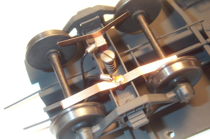
Here is a view of the parts used on the insulated side. The length of the wiper was truncated when the image was processed. Note the phenolic stand-off that raises the wiper above the channel section of the truck bolster. Also note the 0-80 plastic screw that keeps everything insulated from the truck frame. Wire lugs like that shown are available from me; they are sized for either 0-80 (1.7MM screws also work in the #0 hole) or 2-56 screws, and will accommodate up to 22 gauge wire. With them the wiring is a lot cleaner in appearance and much easier to work with if something has to be maintained or tweaked.
Note in the first photo above that the wiper
tab has been bent 90 degrees and that the wiper has been trimmed so
that it clears the insulating bushing on the wheel center.
This photo shows the parts used on the uninsulated side of the truck.
Note that the screw is now brass since it is not necessary to insulate
this side from the truck frame. A separate wiper is used, one for
each axle, because that is simpler. Note in the first photo that the
wipers have been bent into a "gull wing" (anybody remember the F4U
Corsair?) shape in order to clear the channel.
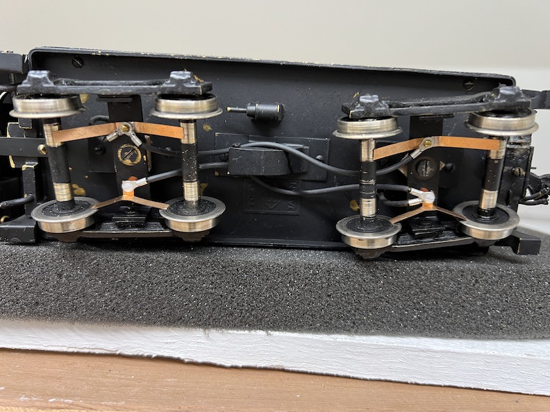
Explanation of the wiring. Each side of both trucks is wired together. One wire from each
side then enters the tender body where additional conventional wiring was completed.
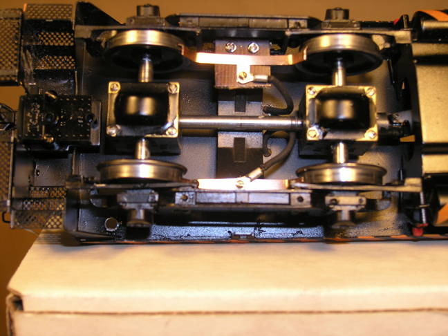
This photo shows wipers installed on the insulated side of of the rear truck on a Key F A unit. The brass wiper mount stand-off (see parts photo below) is mounted in a plastic strip that has been machined to fit the truck/bolster joint. The plastic strip mount insulates the wiper assembly from the truck frame.
Two wire runs come off the post. One run goes inside the body where it
joins the lead from the front truck before being joined to the DCC
decoder. The other wire run goes to a connector behind the unit. A
similar connector comes forward from the front truck on the B unit.
Thus the "electrical sides" of the A and B unit are joined together
(left side to left side, etc.) to give 16 wheel pickup (8 wheels per
side.)
This view shows the wiper assembly separated from the truck. Several
pieces of paper were inserted under the assembly to make things more
visible. The dark pointed area through which one wire run passes is
where the three pieces of paper meet. The main purpose of this photo is
to show you the sequence of assembly of the wiper, and how the plastic
block was machined for a compatible fit with the sideframe and
bolster.
This view shows wipers installed on an Orientl Limited SW-7.
Note that the wipers on the insulated side are mounted to a
piece of phenolic sheet in order to insulate them from the
truck. Also note the flanges on the
insulated wipers which serve to keep
them from moving off the wheel as the wheelset moves from side
to side during normal running.
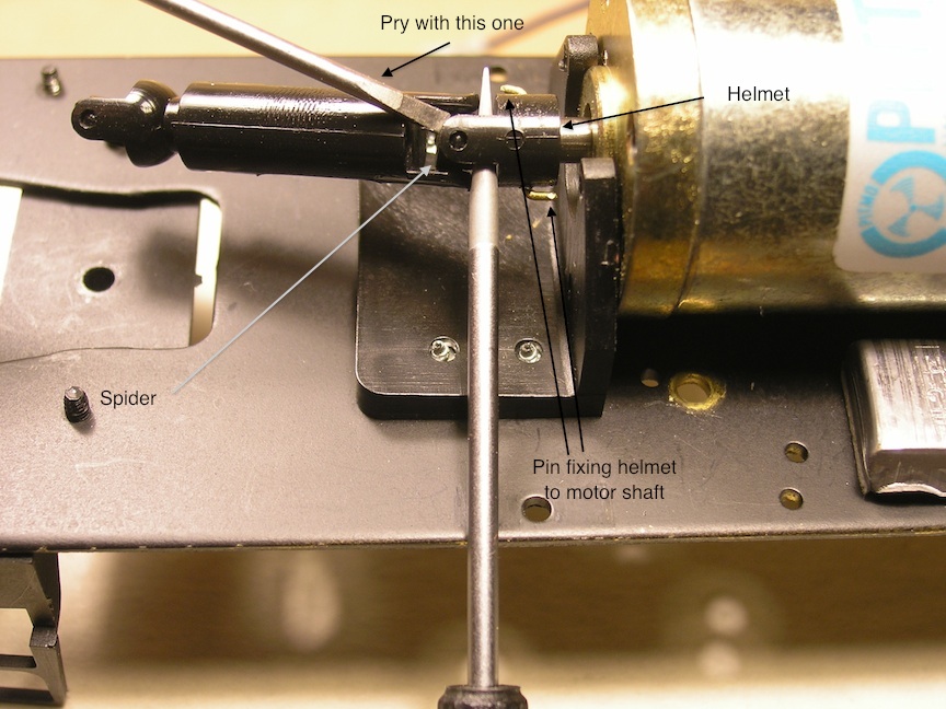
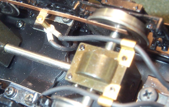
On to the P&D trucks. To remove the truck with the drive tower on it, disconnect the u-joint from the "helmet" (think of a 1920's football helmet with a flat top) that is pressed onto the upper tower shaft. My technique is to insert a tool such as the shaft of a screwdriver between the center "spider" and the helmet - this prevents the spider from pivoting as you use a second tool (I use a small flat blade screwdriver) to pry on the "ear" of the helmet until it pops off the spider. See the photo which illustrates the technique using the the helmet on the motor shaft - you will need to separate this helmet if it is split, see below. Use the same technique if needed to separate the trucks (I say "if needed" because on the A and B units that were being worked on when this section was developed, the shaft between the trucks on one unit just slid together, while the same shaft on the other unit required separation at a helmet to separate the trucks.)
Once the trucks have been removed from the chassis, remove the spring planks by removing the bolsters (4 screws) and the springs (push towards the inside of the truck to remove), then slide the plank out to the side.
TIP: while you have the chassis out of the unit, inspect the
helmet on the motor shaft. On both units, which were older,
one helmet was split and the other was mis-installed on the
motor shaft, allowing it to slip. If you find a problem with
the helmets, you can send the motor and helmet to me. I will
replace the helmet with the same item from my stock but
machined so it is a slip fit (won't split) on the motor
shaft and pinned in place - see the photo above.
The cost for this is $25 plus return
shipping. P&D may perform the repair, possibly for less so
check with them too.
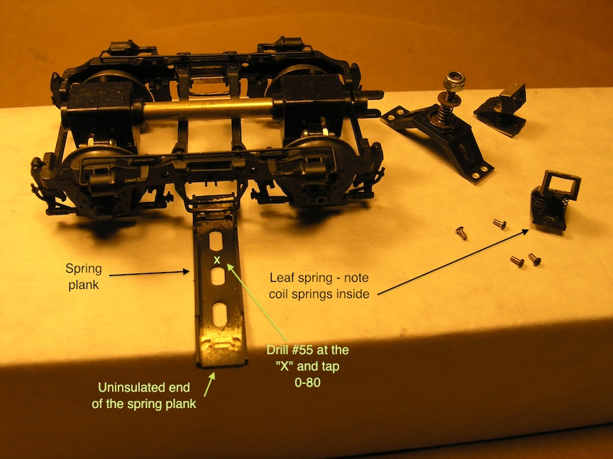
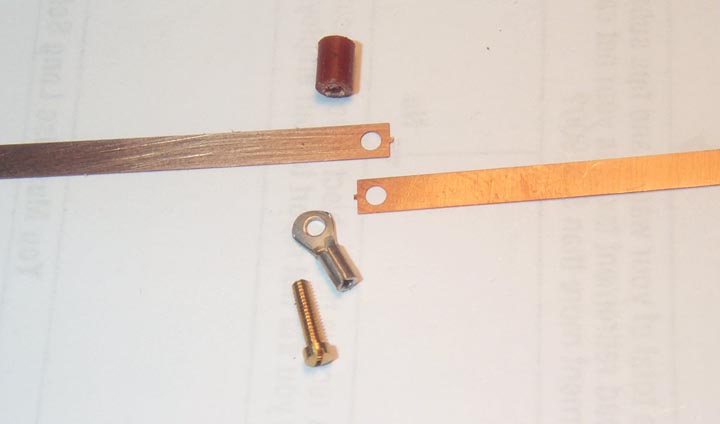
The above photo shows the spring plank removed from the P&D truck along with the parts that had to removed in order to get the plank out.
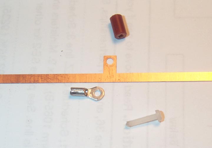
Drill the spring plank #55 as shown. Tap the hole 0-80 or 1.7MM.
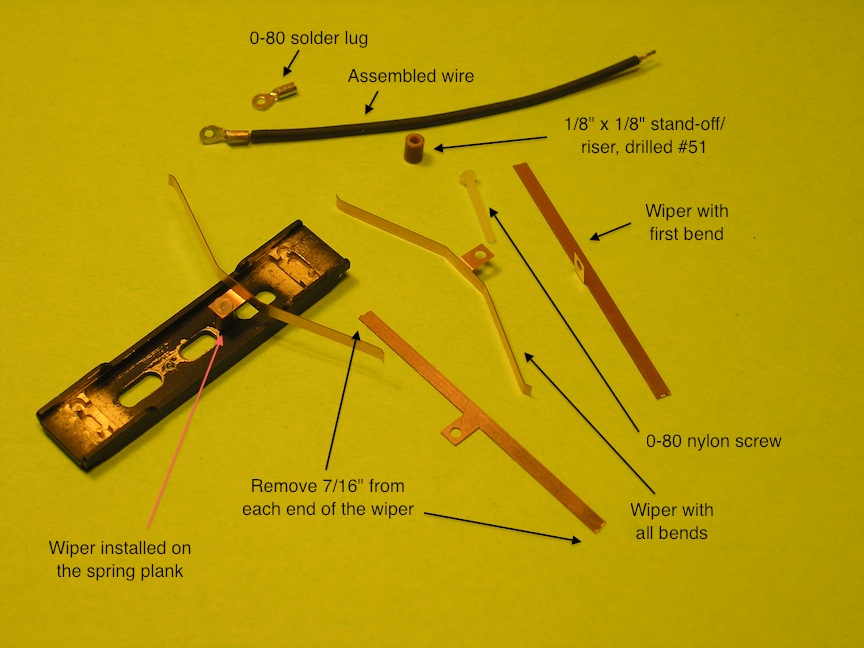
Above are the parts needed to install the wipers. One wiper is shown installed on the plank, but note that you cannot insert the plank into the truck with the wiper installed - you have to install the wiper after the plank has been installed in the truck.
Some notes on the parts used. The wipers, obviously, are available from me. The phenolic stand-offs/risers are 1/8" diameter x 1/8" long - the length is critical for the wiper to clear the metal parts of the truck; I will make them for you at a cost of $20 for four plus $5 for every additional four; ready-made risers may be available - sometimes it is faster for me to make something than to take the time to look for it particularly if experience dictates the size is outside what is normally available. The nylon screws are NWSL #14126-5 (that may be the 100 count pack number). The wire is Belden 24 gauge black rubber coated test lead wire; I like it because it is super flexible. It is available from me for $1.00 per foot.
You may note there are two holes drilled in the plank rather
than the one I indicate above. Sometimes it is faster to have an
extra hole in something that is symmetric and that can be installed
backwards (drilled hole on the uninsulated side - oops), then just
use the "extra" hole. Faster than taking the incorrectly installed
part out and re-installing it.
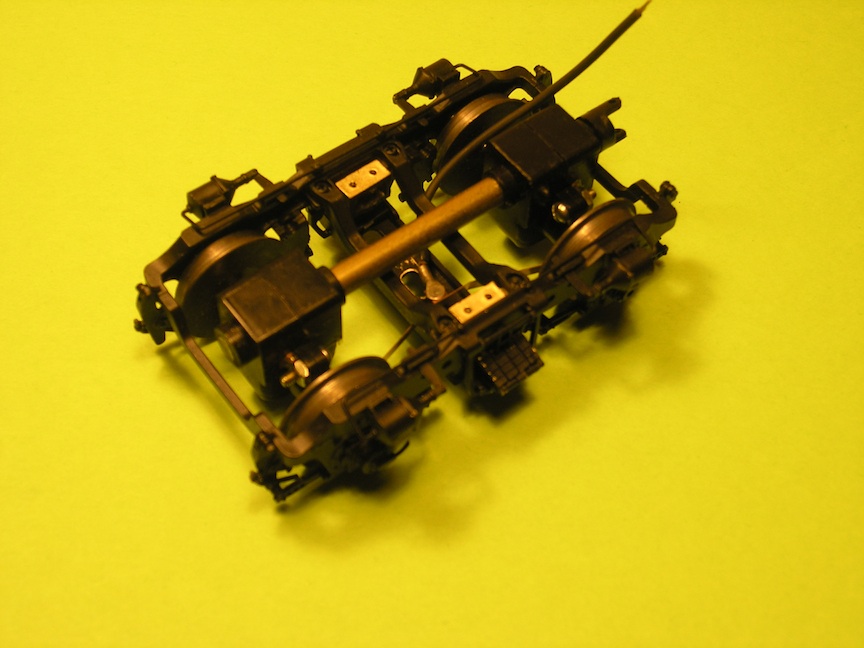
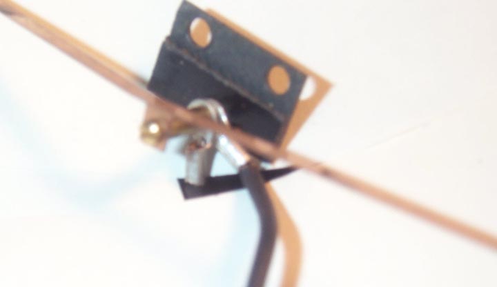
Here is the truck with the wiper installed. It is tricky working inside that space. Make sure the springs are properly seated and that the bolster can be installed (screw holes line up) before installing the wiper. A small dab of grease on the risers will help keep them in position. Put the wiper by itself into position first, then add the other parts. A screw holding screw driver also helps to get everything lined up and the screw started in its hole, I also used some long tweezers on the solder lug to keep the lug in position. Once the screw is home (don't tighten it so much that you strip the soft threads), cut off the excess from the bottom of the plank. The photo is slightly out of focus with respect to the truck itself as I wanted the screw head and solder lug to be in focus.
There are some gotchas with these trucks. They are easy to remedy and if you know about them in advance, your trouble shooting should go easier.
- P & D made two different kits for these trucks, one for F units and one for GP-9s. They are not interchangable because they have different height bolsters. The bolsters for the GP-9 have the letters G P cast into the underside of the bolster (the bolster is the part with the king pin screw to attach the truck to the frame).
- Since the parts are castings, their shape may vay slightly from the process of being cast. One issue I've encountered is the brass tube covering the shafts between the gear boxes would rub on the bottom of the bolster. File a slight clearance notch in the bolster.
- The king pin screw will rub on the the aformentioned tube if it is turned the wrong way, e.g., when the nut on it has been turned to the point where it is too tight and removing it causes the king pin screw to turn in the bolster which causes it to back out of its hole towards the tube.
- Again dependent upon the casting process, a wiper on the insulated side may contact the underside of the bolster, causing a short. File a notch in the bolster to clear it. Putting heat shrink tubing over the wiper will temporarily remove the short but over time abrasion will wear through the heat shrink tubing and the short will be back. Bending the tab on the wiper to mount it upside down may not work, and when you bend the tab back to its original position it may break off - if you have extra wipers you can experiment. Filing a notch in the wiper will weaken the spring of the wiper; reenforcing the wiper by soldering a suitable backing to it at the notch is untested and may work.